The visual success of a minimalist Scandinavian kitchen is determined entirely by the polypropylene waste manifold hidden inside the sink base cabinet. I specify this concealed plumbing assembly during the initial millwork shop-drawing phase, long before finalizing the stone countertop cutout or basin depth. Treating the drain assembly as a rough-in afterthought guarantees a spatial collision inside the cabinetry.
How the Polypropylene Manifold Dictates Base Cabinet Architecture
Modern Nordic kitchen architecture relies on uninterrupted horizontal lines and handleless, full-extension pull-out drawers for integrated waste sorting. Traditional center-drop traps hang 220 mm to 280 mm directly below the basin outlet, intersecting the top 90 mm of standard upper pull-out bin frames. When the plumbing drops straight down from the drain center, cabinetmakers are forced to notch ugly U-shaped cutouts into the top drawer box or sacrifice the upper sorting tier entirely.
Routing the horizontal collector arm immediately behind the basin wall resolves this conflict. Standard Scandinavian sink base cabinets rely on a 65 mm to 80 mm rear service cavity between the removable carcass back panel and the structural masonry wall to house the offset manifold. By tucking the horizontal plumbing run into this narrow rear void, the entire interior volume of the cabinet remains open for full-depth sorting containers.
Every under-sink drainage specification must coordinate four distinct hydraulic zones as a single rigid assembly:
- The waste outlet basket: The primary mechanical sieve and seal interface bolted through the basin floor.
- The overflow conduit: The secondary bypass channel routing excess surface water from the upper perimeter slot back into the main vertical drop.
- The rear-offset manifold: The horizontal collector arm that shifts the drainage axis backward into the service cavity.
- The water trap: The vertical hydraulic seal located flat against the back panel to block sewer gases.
Basket Strainers, Pop-Up Actuators, and Overflow Conduit Geometry
Early specifications frequently paired flush PVD-coated strainer baskets with rotary cable-driven pop-up actuators mounted to the stone deck. Maintenance concerns over congealed culinary fats seizing the inner Bowden cable sheath prompted a shift toward manual two-stage basket strainers with ball-detent stems. Eliminating the eccentric actuator cable removes a snag hazard above the waste bins and preserves a reliable mechanical seal.
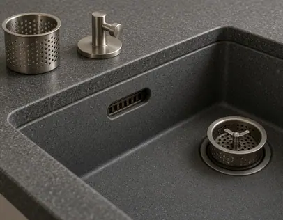
Above the main drain, basin aesthetics have shifted away from stamped circular hole patterns toward flush rectangular or concealed slot overflows. In high-grade brushed stainless steel basins, the passive chromium oxide surface layer naturally resists biological fouling and corrosion along the wet perimeter. However, the concealed geometry behind that slot requires precise hydraulic pitching. Rectangular slot overflows require a minimum 15-degree downward pitch immediately behind the basin flange to prevent stagnant rinse water from pooling against the silicone gasket.
Chromium Oxide Gasket Protection
While the self-healing chromium oxide film on milled stainless steel prevents pitting around the overflow opening, standing water trapped behind an unpitched flange will degrade the elastomeric sealing washer and breed anaerobic bacteria out of reach of surface cleaning.
The conduit connecting that perimeter slot to the main outlet body determines whether the sink develops chronic odors. Many stock basin kits supply corrugated flexible plastic hoses because they bend easily during installation. In a kitchen environment, those internal ribs act as baffles that catch emulsified grease, coffee grounds, and organic film. Specifying smooth-bore rigid polypropylene overflow conduits maintains a self-scouring flow velocity of nearly 0.75 m/s when the main basin drains under a full water head, stripping particulates from the tube walls before biofilm can anchor.
Water Trap Hydraulics: Concentric Bottle Traps vs. Swept Tubular Traps
European drainage standard EN 274 sanitary waste fitting standards mandates a minimum 50 mm water seal depth inside the trap body to prevent sewer gas intrusion during negative pressure fluctuations in the main soil stack. Maintaining that 50 mm barrier under heavy kitchen organic loads depends entirely on the internal curvature of the trap.
Concentric bottle traps force wastewater through two abrupt 180-degree directional reversals within a 60 mm diameter chamber, causing suspended coffee grounds and cooled animal fats to drop out of suspension. While brass or polymer bottle traps perform admirably below bathroom washbasins that handle only soap and cold water, they choke rapidly under culinary starch and lipid discharges. As solids settle at the bottom of the vertical cup, the effective flow cross-section narrows, killing discharge momentum.
Internal trap geometry affects drainage under heavy starch and emulsified lipid loads. Specifiers replaced vertical concentric bottle traps with swept-bend tubular U-traps and S-traps to address persistent slow-draining complaints in open-plan apartments. We gladly trade a slightly wider horizontal footprint for continuous laminar flow that flushes heavy solids through the weir in a single discharge cycle.
Sequencing Dishwasher Spigots and Double-Bowl Manifolds
Combining a deep primary washing bowl, a shallow prep sink, and a high-temperature dishwasher pump into a single concealed trap requires strict vertical sequencing along the drop tube. Installers must order the junctions by flow pressure to prevent cross-flow contamination and acoustic noise.
- Route the gravity anti-siphon loop: Dishwasher drain hoses must be routed to an upper cabinet bracket 650 mm to 750 mm above the finished floor before dropping into the manifold spigot to establish a gravity anti-siphon loop. This elevation barrier prevents foul sink greywater from backing down into the appliance sump when a full basin is released.
- Orient the appliance wye-branch: Position the dishwasher inlet directly on the vertical drop tube above the trap water line. Appliance spigots angled at 45 degrees toward the direction of flow reduce acoustic turbulence in thin-walled stainless steel basins close to 1.2 mm thick during 65°C pump-out cycles. A perpendicular 90-degree spigot blasts pressurized water against the opposite wall of the drop tube, sending a hollow drum resonance up through the open strainer basket.
- Merge the secondary prep bowl: Connect the secondary prep bowl via a swept tee higher up the manifold above the appliance junction. Separating the gravity drain of the prep sink from the pressurized appliance zone stops pumped greywater from surging upward toward the shallower secondary strainer.
This single-trap manifold geometry requires one strict hydraulic boundary: merging two basins and a dishwasher into a single 40 mm shared trap without an integrated air admittance valve is restricted to horizontal cabinet runs shorter than 1.2 meters. Whenever a concealed horizontal run toward a corner soil stack exceeds 1.2 meters, the unvented pipe lacks sufficient air replacement, and the momentum of the draining water column will pull the 50 mm water seal straight out of the trap via induced siphonage.
Millwork Clearances and Tool-Free Maintenance Access
A concealed waste system succeeds only if the homeowner can service the trap without dismantling the kitchen cabinetry or calling a plumber. Final millwork coordination establishes the exact vertical elevation of the trap union nuts relative to the bottom cabinet shelf and the upper edge of the waste bins.
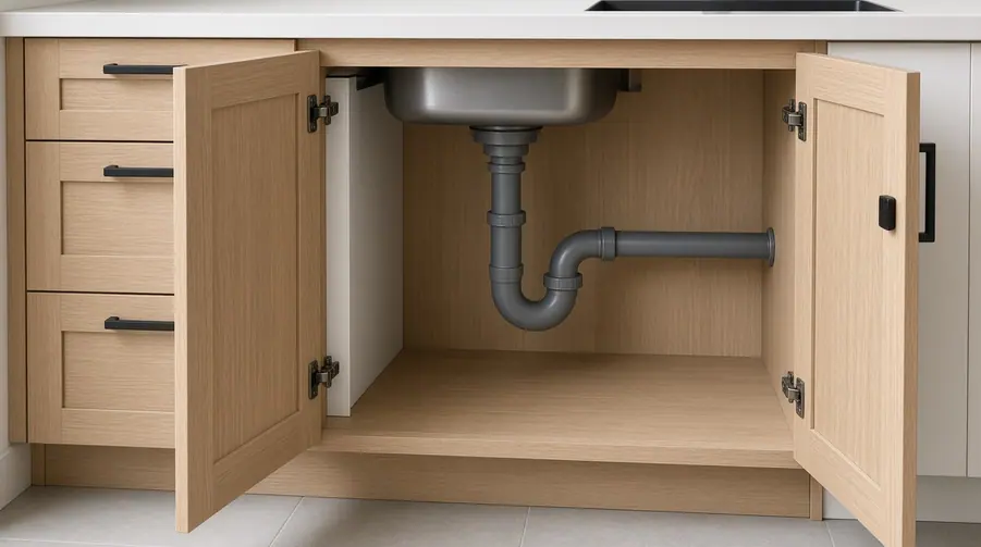
A minimum 110 mm vertical clearance below the lowest point of the tubular trap cup is required to slide a 40 mm deep catch tray underneath and drop the swivel bend clear of the upper spigot threads. With this clearance built into the shop drawings, the user simply pulls the lower waste-sorting drawer out, sets a shallow pan on the cabinet floor, and unscrews the union slip nuts by hand.
Loosening those hand-tightened slip nuts will shift the upper gaskets unless the horizontal manifold is mechanically anchored. By fixing a rigid standpipe clip directly to the rear cabinet rail, the horizontal collector arm remains locked at a constant gradient while the lower U-bend drops away. That single structural bracket also prevents a severe thermal failure mode inside the cabinet: unclipped horizontal polypropylene collector pipes spanning more than 400 mm will sag 8 mm to 14 mm when subjected to continuous 60°C to 70°C dishwasher discharge, creating a permanent back-fall pocket that turns the offset arm into a stagnant grease trough.