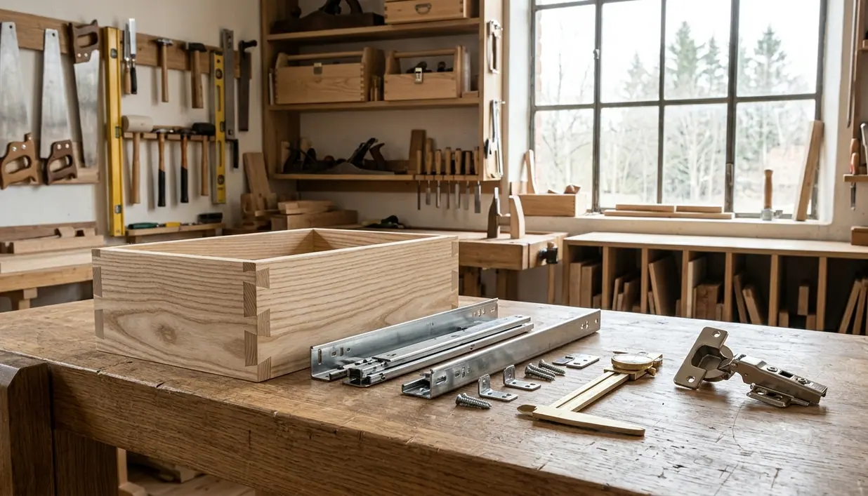
When a Failed Actuator Puts the Cabinet Front at Risk
A concealed actuator can put an entire cabinet front at risk when its replacement requires cutting into the joinery. In a Scandinavian kitchen, that front may carry carefully matched timber veneer or honed stone selected to read continuously across several cabinets. Disturbing it can unravel far more than the opening mechanism.
The cost follows the construction. A proprietary runner may sit behind an adhesive-bonded stone front; a motor housing may occupy a pocket routed specifically for its shape. Removing the front risks cracking the stone along its veining. Enlarging the pocket to accept another mechanism removes timber from the surrounding frame.
This is where apparently discreet technology can become an architectural liability. Timber and stone belong to a long maintenance cycle. Connected receivers, companion apps and sealed actuators introduce another cycle, governed by component availability and software support. The cabinet ties those cycles together whenever the installer makes the electronics inaccessible.
Specify the replacement route alongside the opening action. Ask how a technician reaches the mechanism, which fasteners come out, and whether the decorative front stays attached throughout the repair. A convincing answer should describe a physical sequence.
For a pale oak kitchen with continuous grain across drawer fronts, that sequence deserves the same attention as the veneer layout. Accessible hardware protects the material decisions that give the room its coherence.
Separate the Wear Parts from the Timber Fixings
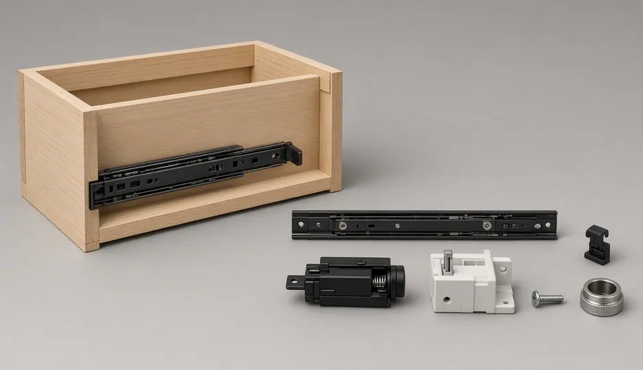
A serviceable runner separates the component that slows the drawer from the assembly that carries its weight. The hydraulic or pneumatic damper handles the final closing movement; the carriage and tracks support and guide the drawer. These parts perform different jobs and should have distinct replacement paths.
During sample review, release the drawer and locate the damping unit. Look for a clip, catch or accessible fixing that allows the unit to come away independently. Replacing a worn damper should leave the carcass tracks and their timber fastenings undisturbed.
Keep the Mounting Plate in Place
A three-way adjustable European cup hinge offers control over depth, height and side-to-side overlay. Those adjustments let the installer align door faces while retaining the carcass fixing positions. A detachable hinge body adds another useful separation: the moving mechanism can come off while its mounting plate stays secured to the birch plywood or high-density fiberboard core.
The familiar 35mm cup format provides a useful starting point for comparison. Check the plate connection, fixing pattern and replacement hinge together, rather than assuming that the cup diameter establishes complete compatibility. On thin stone or ceramic fronts, specify a suitable backing frame to accommodate the hinge recess.
Ask separately whether the spring or damper can be replaced, or whether servicing requires a complete hinge body. Stainless steel's chromium oxide surface protection concerns corrosion; access to those moving parts determines how the fitting gets repaired.
Trace the Power Supply Before Opening the Joinery
Consider an overhead cabinet with a heavy timber door and a motorized lift. When the door stops moving, the useful first question concerns access: can someone reach the power supply, controller and lift mechanism without dismantling the cabinet?
A transformer tucked behind a fixed toe-kick creates a different repair task from one mounted behind a removable access panel. Heat trapped near an oven can degrade electrical components, while an inaccessible installation makes even a straightforward component exchange disruptive. The same access review belongs around sensor strips exposed to kitchen grease and humidity.
App control introduces a separate dependency. A discontinued companion app or an incompatible update can interrupt the control route while the timber enclosure remains sound. Before specifying connected opening, establish how the cabinet operates locally and how its door can be released during a power or control fault.
Compare the Actual Repair Movements
A mechanical counterbalance stay offers a visible adjustment point: its accessible tension screw lets the mechanism accommodate the door's weight. A seized motorized arm concealed behind a fixed panel may require removing joinery before the technician can reach the fault. Compare those physical tasks at the drawing stage.
Apply the same scrutiny to lighting and servo wiring. Removable channels and accessible connections give electrical parts a route out. Bonding those assemblies directly into panels ties their replacement to the cabinet fabric. Mark the access panels on the construction drawings, including the space needed to withdraw each component.
Make Spare-Part Access Part of the Hardware Order
The showroom test rewards a quiet close and a satisfying opening movement. Procurement needs a second test: take the sample apart. Put the runner, damper, clips and mounting plates on the table, then match each replaceable item to an orderable part.
A stamped identifier on a subcomponent gives the maintenance team something concrete to follow. Confirm that the supplier sells that component independently; a visible number alone does not establish a purchasing route.
Questions for the Technical Submittal
- Spare-part commitment: What duration of backward-compatible parts supply will the manufacturer put in writing?
- Wear-component replacement: Can dampers, rollers and synchronization rods be ordered separately?
- Carcass protection: Which repairs leave the original timber fixing screws untouched?
- Drilling compatibility: Does the installation use the System 32 grid, and which mounting plates fit it?
- Electrical access: Can power supplies, sensors and drives be removed through the planned openings?
- Maintenance records: Will the handover package identify installed parts and show their removal sequence?
Keep an exploded drawing and the accepted component schedule with the kitchen documentation. These give a future repairer a useful starting point even after the original installer has moved on.
The enduring detail is remarkably small: System 32 places 5mm holes at 32mm centres, with the front row set back 37mm from the carcass edge. A future hardware decision can begin with those holes already waiting in the timber.